

1. ESP32-S3-DevKitC Pinout
The ESP32-S3-DevKitC -1 is an entry-level development platform built around the ESP32-S3-WROOM-1 or ESP32-S3-WROOM-1U modules. These general-purpose modules integrate comprehensive Wi-Fi and Bluetooth Low Energy (BLE) functionalities.
For prototyping efficiency, most of the I/O pins on the integrated module are broken out to the dual-row pin headers on both sides of the board. Developers have the flexibility to interface with peripherals using jumper wires or mount the ESP32-S3-DevKitC -1 directly onto a standard breadboard.
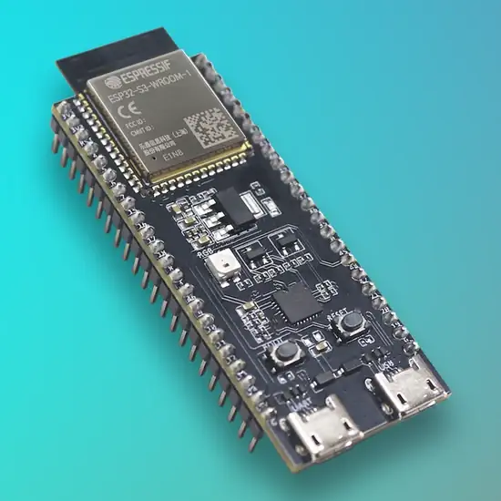
ESP32-S3-DevKitC Pinout
1.1 Getting Started
This section provides a brief introduction to the board, alongside hardware setup instructions and firmware flashing procedures.
1.1.1 Required Hardware
1.1.2 Module Configuration Options
The board supports various module versions based on Flash memory capacity and PSRAM availability:
1.1.3 Contents and Packaging
The development board has a variety of variants to choose from, as shown in the table below.
| Ordering Code | Module Integrated | Flash | PSRAM | SPI Voltage |
| ESP32-S3-DevKitC-1- N8R8 | ESP32-S3-WROOM-1- N8R8 | 8 MB QD | 8 MB OT | 3.3 V |
| ESP32-S3-DevKitC-1- N32R16V | ESP32-S3-WROOM-2- N32R16V | 32 MB OT | 16 MB OT | 1.8 V |
| ESP32-S3-DevKitC-1UN8R8 | ESP32-S3-WROOM-1UN8R8 | 8 MB QD | 8 MB OT | 3.3 V |
2. Hardware Reference ESP32-S3-DevKitC Pinout
2.1 Component Description and Functional Block
The following table outlines the essential hardware blocks of the development board ESP32-S3-DevKitC Pinout:
| Component | Technical Description |
| ESP32-S3 Module | Central processing unit managing wireless and logic tasks. |
| 5V to 3.3V LDO | Onboard low-dropout regulator for voltage stabilization. |
| USB-to-UART Bridge | Micro-USB port for serial debugging and firmware flashing. |
| Native USB Port | Full-speed USB OTG interface integrated into the S3 SoC. |
| Boot Switch | Tactical switch for firmware download mode entry. |
| Reset Switch | Tactical switch for immediate system hardware reset. |
| RGB LED | Programmable WS2812 multi-color LED (GPIO48). |
| Status LED | Visual indicator for active power supply. |
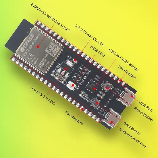
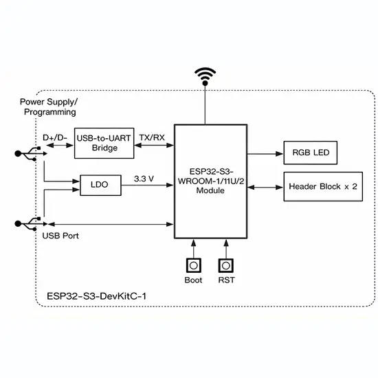
3 Pinout Reference ESP32-S3-DevKitC Pinout
This section details the hardware signal mapping for the J1 and J3 headers.
J1 Header Specifications (Left Side)
| Pin | Name | Hardware Assignment |
| 1 | 3V3 | 3.3V Power Rail |
| 2 | 3V3 | 3.3V Power Rail |
| 3 | RST | CHIP_PU (System Reset) |
| 4 | 4 | GPIO4, ADC1_CH3, TOUCH4 |
| 5 | 5 | GPIO5, ADC1_CH4, TOUCH5 |
| 6 | 6 | GPIO6, ADC1_CH5, TOUCH6 |
| 7 | 7 | GPIO7, ADC1_CH6, TOUCH7 |
| 8 | 15 | GPIO15, ADC2_CH4, TOUCH15 |
| 9 | 16 | GPIO16, ADC2_CH5 |
| 10 | 17 | GPIO17, ADC2_CH6 |
| 11 | 18 | GPIO18, ADC2_CH7 |
| 12 | 8 | GPIO8, ADC1_CH7, TOUCH8 |
| 13 | 19 | GPIO19, USB_D- |
| 14 | 20 | GPIO20, USB_D+ |
| 15 | 3 | GPIO3, ADC1_CH2, TOUCH3 |
| 16 | 46 | GPIO46 (Input only) |
| 17 | 9 | GPIO9, ADC1_CH8, TOUCH9 |
| 18 | 10 | GPIO10, ADC1_CH9, TOUCH10 |
| 19 | 11 | GPIO11, ADC2_CH0, TOUCH11 |
| 20 | 12 | GPIO12, ADC2_CH1, TOUCH12 |
| 21 | 13 | GPIO13, ADC2_CH2, TOUCH13 |
| 22 | 14 | GPIO14, ADC2_CH3, TOUCH14 |
| 23 | 5V | 5V External Input Rail |
| 24 | G | Ground (GND) |
J3 Header Specifications (Right Side)
| Pin | Name | Hardware Assignment |
| 1 | G | Ground (GND) |
| 2 | 45 | GPIO45 functional pin |
| 3 | 48 | GPIO48 (RGB LED control) |
| 4 | 47 | GPIO47 functional pin |
| 5 | 21 | GPIO21, ADC2_CH10 |
| 6 | 35 | GPIO35, ADC2_CH4 |
| 7 | 36 | GPIO36, ADC2_CH5 |
| 8 | 37 | GPIO37, ADC2_CH6 |
| 9 | 38 | GPIO38, ADC2_CH7 |
| 10 | 39 | GPIO39, ADC2_CH8 |
| 11 | 40 | GPIO40, ADC2_CH9 |
| 12 | 41 | GPIO41 functional pin |
| 13 | 42 | GPIO42 functional pin |
| 14 | 2 | GPIO2, ADC1_CH1 |
| 15 | 1 | GPIO1, ADC1_CH0 |
| 16 | 0 | GPIO0 (Boot Strapping) |
| 17 | 33 | GPIO33 functional pin |
| 18 | 34 | GPIO34 functional pin |
| 19 | 43 | GPIO43, U0TXD (TX) |
| 20 | 44 | GPIO44, U0RXD (RX) |
| 21 | G | Ground (GND) |
| 22 | G | Ground (GND) |
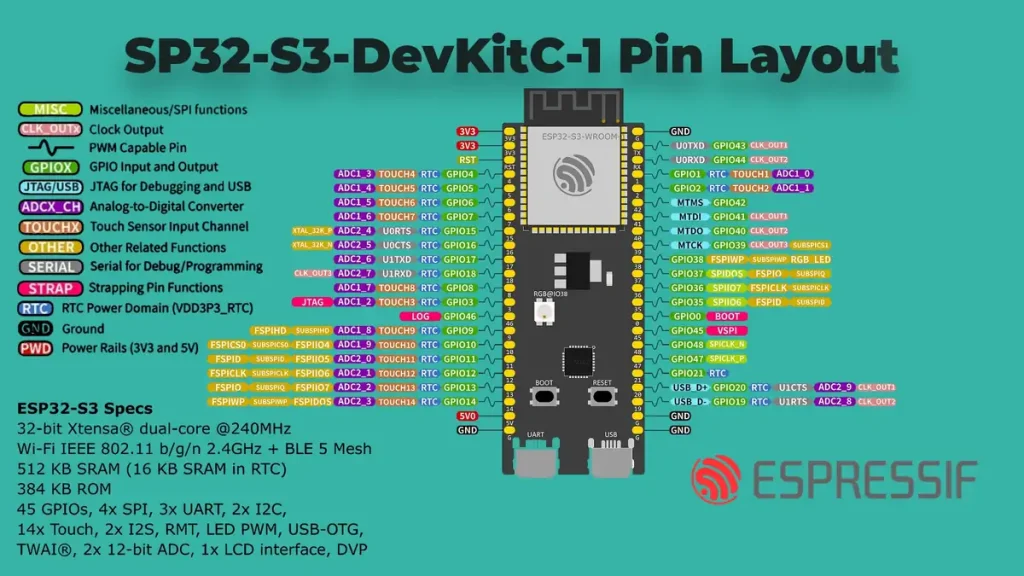
4 Power Supply Options ESP32-S3-DevKitC Pinout
The development kit can be energized using three mutually exclusive power input methods:
Caution: Avoid simultaneous power supply to multiple inputs to prevent hardware damage.
References & Legal Notice
This technical manual is developed based on the official documentation provided by Espressif Systems. We highly recommend referring to the primary source for the most recent updates regarding hardware revisions and detailed specifications.
Disclaimer: ESP32 and ESP32-S3 are registered trademarks of Espressif Systems (Shanghai) Co., Ltd. This guide is an independent technical review and is not an official publication of Espressif Systems.