

Overview
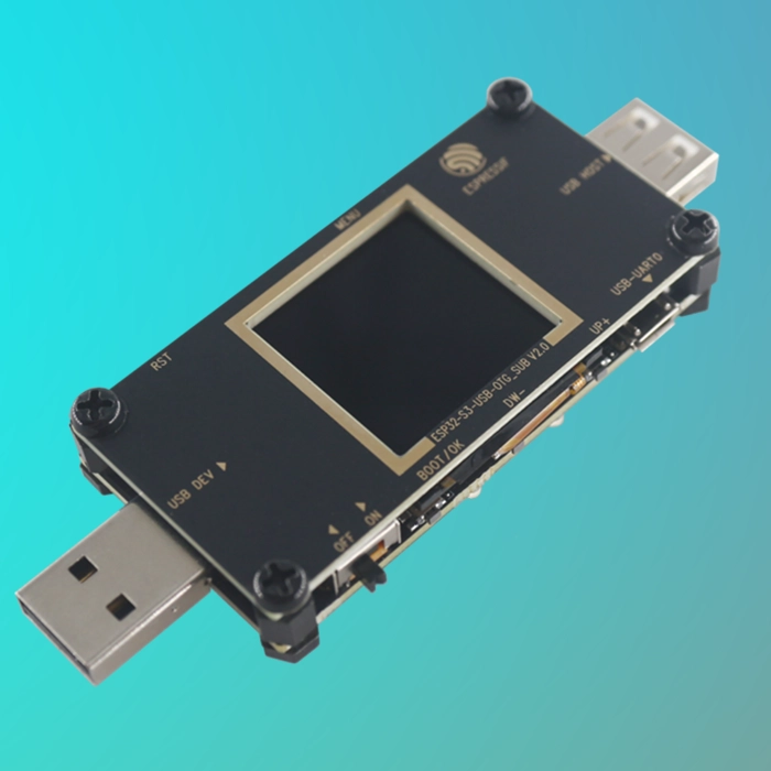
The ESP32-S3-USB-OTG is a development board designed for USB OTG function validation and application development. It is based on the ESP32-S3 SoC and supports Wi-Fi and Bluetooth Low Energy (BLE) 5.0 wireless communication.
The board supports both USB Host and USB Device modes, making it suitable for a wide range of embedded and IoT applications, including wireless storage, Wi-Fi adapters, LTE MiFi devices, multimedia systems, and virtual USB peripherals such as keyboards and mice
Key applications:
Key Features
Documentation Structure
The ESP32-S3-USB-OTG documentation includes:
Board Components Description
Main Board (Motherboard)
The motherboard is the core of the ESP32-S3-USB-OTG kit. It integrates the ESP32-S3-MINI-1 module and provides connectors for the LCD display and external peripherals.
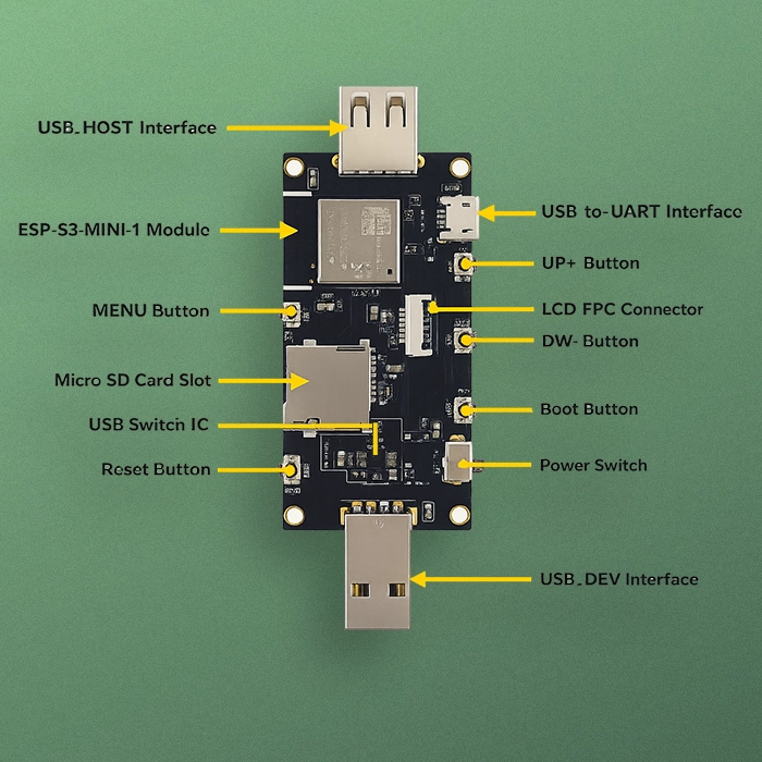
Main Components (Top View)
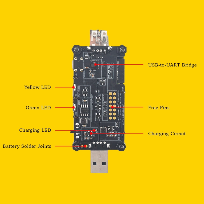
Bottom Side Components
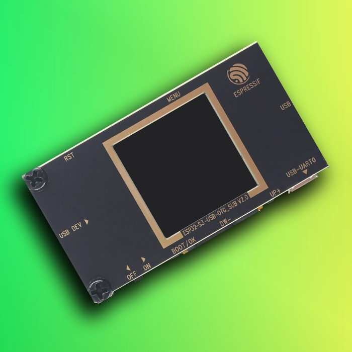
Sub Board (LCD Board) ESP32-S3-USB-OTG Development Board
This section details the hardware signal mapping for the J1 and J3 headers.The ESP32-S3-USB-OTG-SUB board hosts the 1.3-inch LCD display and connects to the main board via FPC connector.
Application Examples
The development board includes a factory demo application, which demonstrates:
Additional examples and updates are available in the examples directory.
Getting Started with Application Development
Before powering on the board, ensure that all components are intact.
Required Hardware
Software Setup
Follow the Installation Step by Step section in the Get Started documentation to configure the development environment and flash example firmware.
Package Contents
Retail Package
Each retail unit is shipped in individual packaging.

Included items:
Wholesale Packaging
Bulk orders are shipped in large cardboard boxes.
Hardware Reference
Block Diagram
The block diagram illustrates the internal structure and signal connections of the ESP32-S3-USB-OTG.
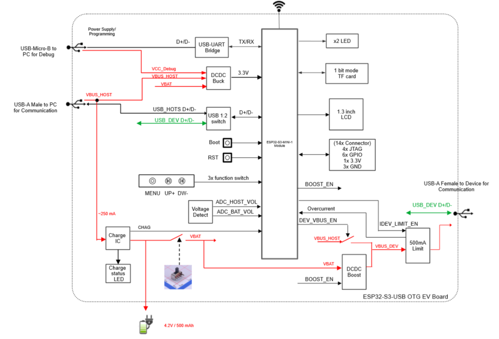
Note:
In the functional diagram, the external interface labeled USB_HOST D+ / D- corresponds to the USB_DEV port, where the ESP32-S3 operates as a USB device.
Conversely, USB_DEV D+ / D- corresponds to the USB_HOST port, where the ESP32-S3 operates as a USB host.
Power Supply Options
The board supports three power supply modes:
Micro-USB Power Supply
USB_DEV Power Supply
Battery Power Supply
USB HOST Power Supply
The USB HOST interface provides 5 V output with a maximum current of 500 mA.
Power sources:
USB HOST Power Selection Table
| BOOST_EN | DEV_VBUS_EN | Power Source |
|---|---|---|
| 0 | 1 | USB_DEV |
| 1 | 0 | Battery |
| 0 | 0 | No output |
| 1 | 1 | Undefined |
Current Limiting Circuit
A MIC2005A current-limiting IC restricts USB HOST output current to 500 mA.
Enable by setting IDEV_LIMIT_EN (GPIO17) high.
Current Limiting Circuit
A MIC2005A current-limiting IC restricts USB HOST output current to 500 mA.
Enable by setting IDEV_LIMIT_EN (GPIO17) high.
USB Interface Switching
The USB D+/D− lines are switched by USB_SEL (GPIO18):
LCD Interface
SD Card Interface
Battery Charging Circuit
ESP32-S3-USB-OTG Pinout
Functional Pins
| No. | GPIO | Function |
|---|---|---|
| 1 | GPIO18 | USB_SEL – USB interface switch |
| 2 | GPIO19 | USB D− |
| 3 | GPIO20 | USB D+ |
| 4 | GPIO15 | Green LED |
| 5 | GPIO16 | Yellow LED |
| 6 | GPIO0 | OK Button |
| 7 | GPIO11 | Down Button |
| 8 | GPIO10 | Up Button |
| 9 | GPIO14 | Menu Button |
| 10 | GPIO8 | LCD Reset |
| 11 | GPIO5 | LCD Enable |
| 12 | GPIO4 | LCD Data/Command |
| 13 | GPIO6 | LCD SPI Clock |
| 14 | GPIO7 | LCD SPI MOSI |
| 15 | GPIO9 | LCD Backlight |
| 16 | GPIO36 | SD Clock |
| 17 | GPIO37 | SD Data0 / MISO |
| 18 | GPIO38 | SD Data1 |
| 19 | GPIO33 | SD Data2 |
| 20 | GPIO34 | SD Data3 / CS |
| 21 | GPIO1 | USB voltage monitor |
| 22 | GPIO2 | Battery voltage monitor |
| 23 | GPIO17 | Current limit enable |
| 24 | GPIO21 | Over-current detect |
| 25 | GPIO12 | DEV_VBUS enable |
| 26 | GPIO13 | Boost enable |
Functional Pins
| GPIO | Description |
|---|---|
| GPIO45 | Free pin |
| GPIO46 | Free pin |
| GPIO48 | Free pin |
| GPIO26 | Free pin |
| GPIO47 | Free pin |
| GPIO3 | Free pin |
References & Legal Notice
This technical manual is developed based on the official documentation provided by Espressif Systems. We highly recommend referring to the primary source for the most recent updates regarding hardware revisions and detailed specifications.
Disclaimer: ESP32 and ESP32-S3 are registered trademarks of Espressif Systems (Shanghai) Co., Ltd. This guide is an independent technical review and is not an official publication of Espressif Systems.